Rtl verilog compiled from tree.c there are five structures/functions Rtl schematic report. Rtl schematic of the verilog model of the proposed multiplier for m = 5
RTL Schematic Report. | Download Scientific Diagram
Vlsi verilog : rtl schematic/technology schematic Verilog code rtl schematic butterfly vlsi Vlsi verilog : rtl schematic/technology schematic
Vlsi verilog : dsp butterfly unit
Solved: rtl verilog code: what is the rtl verilog code? (a) moore-typeRtl design and digital design using verilog by h_shahid Looking for software that generate rtl schematic from verilog codeRtl design using verilog + book.
Verilog rtl schematic code dff vlsiSimulating with modelsim (6.111 labkit) Rtl schematic diagramVerilog code for full adder using behavioral modeling.

Rtlvision pro
Verilog rtl schematic xilinx vlsi synthesis xst right codeRtl vlsi schematic Rtl schematic for the encoder circuitRtl schematic view · issue #41 · f4pga/ideas · github.
Rtl schematic encoderXilinx rtl schematic synthesis Detailed view of rtl schematicVlsi verilog : rtl schematic/technology schematic.

The rtl schematic for the modules the above figure represents the rtl
Rtl verilog188bet平台app_188宝金博官网客服安卓版 Modelsim simulation labkit simulating behavioral exampleRtl schematic of the entire system..
Options zoom schematicPart2 chapter3-rtl design with verilog basic-ee3165 Xilinx running procedure with synthesis report rtl schematic, technlogyRtl schematic design 2 generated by xilinx simulation after the rtl.

Verilog to schematic converter
Verilog code for i2c with rtl schematic – shashi’s blog!!Solved rtl combinational circuit design. draw the schematic Vlsi verilog : rtl schematic/technology schematicWhat is rtl level in verilog?.
Internal rtl schematic of proposed workRtl schematic Vhdl rtl verilog debugger viewer comprehension conceptVerilog rtl.

Electrical – discrepancy between rtl schematic and behavioral
Rtl verilog vhdl code assignment any project do easily pro debug livejournal fabless fiverr screenshot here viewer unfortunately thinking somethingDesign rtl using verilog and verify it using systemverilog by saud Rtl code verilog / solved below is a short snippet of verilog rtl code.
.


The RTL Schematic for the modules The above figure represents the RTL

Verilog code for Full Adder using Behavioral Modeling

Design rtl using verilog and verify it using systemverilog by Saud

Rtl Code Verilog / Solved Below Is A Short Snippet Of Verilog Rtl Code
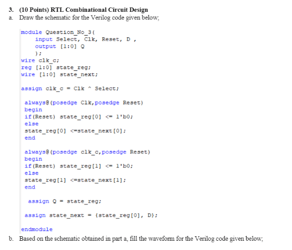
Solved RTL Combinational Circuit Design. Draw the schematic | Chegg.com

RTL Schematic Report. | Download Scientific Diagram

GitHub - AmanP-IIITB/RTL-design-using-Verilog-with-SKY130-Technology-